
树莓派pico入门指南
一.pico引脚图

二.怎样使用pico
首先需要安装thonny,我们在这个软件上为pico编写程序
下面视频中用到的uf2文件和软件都在这里,无需再去下载视频里的文件了
链接:https://pan.baidu.com/s/1LLKOPCaXz0YnRgKDdawKnQ?pwd=uyxt
下面链接中的视频提供了软件安装方法
三.pico点灯(测试用代码)
1 | |
若看到pico上的灯以一秒间隔闪烁一次,则成功
四.oled屏幕
oled相关资料链接:https://pan.baidu.com/s/1nQGsRBe6f7FK12ftu00h7w?pwd=a3b0
向pico导入链接里main.py和ssd1306.py两个文件,在main.py文件里运行即可。可更改main文件,得到不同的输出内容。
使用的是像素点为128x32的oled屏幕,而一个字符是8x8大小的,就是说最多一行输入16个字符,最多有4行,共64个字符
注意:要编写字库后,才能识别汉字和图片
接线方式(方向为pico–oled):
- 3v3–VCC
- GND–GND
- GP6–SDA
- GP7–SCK
输出字符
1 | |
输出数字
1 | |
输出图形
1 | |
其他小技巧
1 | |
中文点阵生成网站: https://www.zhetao.com/fontarray.html
1 | |
五.摇杆模块(ADC)
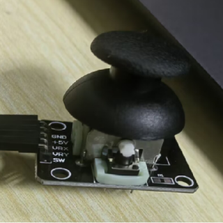
摇杆的x轴和y轴相当于两个独立的滑动变阻器
- 在静止时,摇杆位于滑动变阻器中间位置,此时阻值大约为总阻值的一半。
- 当摇杆移动到一侧时,例如x轴向右移动或y轴向上移动,对应的滑动变阻器的阻值会逐渐减小,最终接近于0欧姆。
- 而当摇杆移动到另一侧时,例如x轴向左移动或y轴向下移动,对应的滑动变阻器的阻值会逐渐增大,最终达到阻值的最大值。
这种阻值的变化导致了模拟信号的分压情况也不同,通过将摇杆输出信号连接到模数转换器(ADC)输入引脚上,单片机可以将模拟信号转换为数字信号进行处理。
因此,在程序设计中,我们可以根据ADC转换后的数字信号值来判断摇杆的具体位置,进而实现相应的功能。
接线方式
摇杆 —– pico
- GND —– GND
- 5v —– GP10
- VRX —– GP26
- VRY —– GP27
- SW —– GP28
注:5v接在GP10上,是因为直接接单片机VBUS(5v),摇杆adc读出来的值不对,你们可以试一下,我也不知道为什么,我测试过3.3v供电,数据才符合,而板子上3.3v用了一个了,这里用gpio输出高电平,也就是3.3v了
但是要先这样声明一下,gpio才会输出高电平
1 | |
adc读取摇杆的值
1 | |
判断摇杆的方向
1 | |
六.蜂鸣器
理论基础请看下面的视频11-1节
接线方式
蜂鸣器 —– pico
- “-” —– GND
- “+” —– GP20
演奏音乐示例代码
若只简单应用,只需修改歌曲内容
1 | |
七.PWM
呼吸灯
1
2
3
4
5
6
7
8
9
10
11
12
13
14
15
16
17
18
19
20
21import time
from machine import Pin, PWM
pwm = PWM(Pin(25)) #把板载led灯的GPIO配置为PWM模式(可以更改为其他引脚,将自己的led灯接在设置的引脚上)
pwm.freq(10000) # 设置PWM频率为10kHz
duty = 0 # 初始化PWM值和方向
direction = 1
while True:
# 根据方向增减值
duty += direction
# 如果值大于65535,则将值设置为最大值,并改变方向为递减
if duty > 65535:
duty = 65535
direction = -1
# 如果值小于0,则将值设置为0,并改变方向为递增
elif duty < 0:
duty = 0
direction = 1
# 设置PWM的值
pwm.duty_u16(duty)PWM舵机
接线方式:舵机——pico
红色线 3.3v
棕色线 GND
橙色线 GP5
1 | |
八.中断
接线方式:
led灯长脚接GP11 ,短脚接GND
摇杆按键SW接GP12,5v接3.3v,GND接GND
1 | |
九.定时器
1 | |
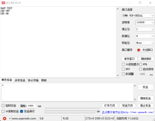
十.串口通信
先从以下链接中下载串口软件
链接:https://pan.baidu.com/s/1VXN6w_Nuc2TFNZ1zu3zozA?pwd=8t1v
接线方式: 串口模块 —— pico
5v——VBUS
GND——GND
TX——GP1(通信双方都是TX和RX交叉连接哦)
RX——GP0
打开串口软件,选择对应串口和波特率,点击开启串口的选项。
在下面输入框按照通信协议输入,点击发送,即可完成电脑向单片机通信。
1 | |
十一.PIO
介绍一个PIO点灯的程序,效率比普通的点灯程序高很多,通过使用单片机上硬件资源,减轻单片机CPU的负荷。
除此之外,PIO可以模拟IIC或VGA等很多单片机上可能没有的通信协议端口,给了开发者非常高的开发自由度,请根据PICO数据手册自行学习
1 | |
十二.自学教程推荐
https://blog.csdn.net/slofslb/category_11328828.html?spm=1001.2014.3001.5482